ATA 100 Chapter System: Origin and Structure
The aviation industry is built on complex aircraft systems, components, parts, procedures, and technical documents.
Because of this complexity, maintenance, repair, engineering, and operational work require a clear and standardized reference structure.
The ATA 100 Chapter System, also known as Air Transport Association Specification 100, was created to meet this need.
It provides a structured coding and numbering method for identifying aircraft systems, subsystems, components, and related maintenance information.
This structure helps cockpit crews, maintenance personnel, engineers, planners, and technical documentation teams speak the same technical language.
Without such a standard, aircraft manuals would quickly turn into a very expensive maze of page numbers, system names, and “good luck finding that valve” energy.
The same logic also applies to the aircraft maintenance documents I explained in this previous article >>>.
Documents such as AMM, IPC, CMM, SRM, TSM, WDM, and other technical references often use this standardized chapter logic.
This makes the system extremely important for anyone who wants to understand aircraft maintenance documentation.
What Is ATA?
ATA stands for Air Transport Association.
The Air Transport Association was founded in 1936 by North American airline operators.
It was based in Washington, D.C. and functioned as a trade association and lobbying organization for the airline industry.
Today, the organization continues under the name Airlines for America, also known as A4A.
The original ATA organization created important standards that helped airlines, manufacturers, maintenance organizations, and technical teams work with more consistency.
One of the most important examples of this standardization effort is the aircraft system chapter numbering structure.
This structure became widely known in aircraft maintenance and engineering documents.
How Was the ATA 100 Chapter System Created?
Air Transport Association of America first created a standard numbering system for aircraft systems on June 1, 1956.
The purpose was to organize aircraft technical information in a consistent way.
Commercial aviation needed a clear structure because aircraft were becoming more technically advanced.
Different manufacturers, operators, and maintenance teams needed a shared method to identify systems and related technical procedures.
Although the numbering system was created mainly for commercial aviation, it has also been used in military aviation contexts.
For example, aircraft such as the F-16 can also use similar chapter-based documentation logic.
The key idea is simple but powerful.
Each major aircraft system receives a chapter number.
Then each system can be divided into smaller subsystems and component-level references.
This allows technical documents to be organized in a predictable way.
For example, if a technician sees Chapter 27, they can understand that the subject is related to flight controls.
If they see Chapter 29, they know the subject is related to hydraulic power.
This saves time, reduces confusion, and improves traceability.
Why This Numbering Structure Matters
Aircraft maintenance depends on accuracy.
Technicians must know which system they are working on, which component is involved, which procedure applies, and which reference document should be used.
A standardized chapter structure helps organize this information clearly.
It supports maintenance, repair, modification, troubleshooting, inspections, component replacement, and engineering analysis.
It also supports training, research, development, logistics, spare part tracking, and airline operations.
For airlines, this kind of standardization can reduce maintenance time and documentation confusion.
For technicians, it helps locate the correct procedure faster.
For engineers, it supports system analysis and technical communication.
For planners, it helps organize tasks, work cards, and maintenance programs.
In short, this numbering method is not only a document layout preference.
It is part of the technical language of aircraft maintenance.
And in aviation, speaking the same technical language is not a luxury.
It is a safety habit.
Chapter and Page Number Logic in Documents
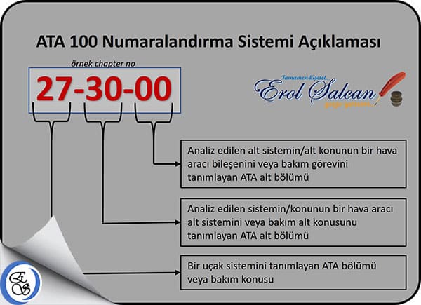
The numbering logic used in aircraft documents usually follows a structured format.
A typical reference such as 29-11-13 can be divided into different meaning layers.
The first two digits usually identify the main chapter.
The next two digits identify the system or subsystem level.
The final two digits can identify a more detailed component or function.
Main Chapter Number: First Two Digits
The first two digits show the main aircraft system category.
For example, Chapter 29 refers to Hydraulic Power.
| Hydraulic Power – General |
In this example, 29 is the main chapter number.
It tells the reader that the subject belongs to the hydraulic power system.
Second Two Digits: System and Subsystem Level
The second pair of digits provides more detailed information inside the main chapter.
In some structures, the first digit of this pair can identify the system level, while the second digit can identify a more specific subsystem.
For example:
| Main | |
| Auxiliary |
A more detailed example can be shown as follows:
| Main | |
| Green Main Hydraulic Power | |
| Blue Main Hydraulic Power | |
| Yellow Main Hydraulic Power |
This structure allows the reader to move from a broad system to a more specific subsystem.
Instead of searching randomly, the technician can follow a logical hierarchy.
Third Two Digits: Component Level
The third pair of digits usually points to a component or more specific technical item within the system.
For example:
| Green Main Hydraulic Power | |
| Green Assembly Reservoir | |
| Hydraulic Reservoir | |
| Green Hydraulic Pump |
This level of detail is extremely useful in aircraft maintenance.
It helps identify exactly which component, subsystem, or reference area is being discussed.
That means fewer misunderstandings and faster technical navigation.
AMM Page Number Meanings
In the Aircraft Maintenance Manual, page numbers can also carry a specific meaning.
Different page ranges may point to different task types or information groups.
This helps technicians understand the type of content they are reading.
| Description and Operation | |
| Troubleshooting | |
| Maintenance Practices | |
| Servicing | |
| Removal / Installation | |
| Adjustment / Test | |
| Inspection / Check | |
| Cleaning / Painting | |
| Approved Repairs | |
| Deactivation / Reactivation |
If the pages for a subject exceed 99 pages, the numbering can continue with A00-style extensions.
For example:
This may look like a small detail, but it is very useful in real maintenance work.
When a technician understands page numbering logic, they can find the correct information faster.
And when an aircraft is waiting for maintenance action, faster access to correct information is not exactly a bad thing.
Main ATA 100 Chapter Numbers
The table below shows main aircraft system chapter numbers and their English and Turkish meanings.
This table is one of the most practical parts of the subject because it gives a quick overview of how aircraft systems are grouped.
ATA 100 Bölüm ve Başlıkları |
||
| Introduction | Giriş | |
| Periodic Inspections | Periyodik Muayeneler | |
| Dimensions and Areas | Boyutlar ve Alanlar | |
| Lifting and Shoring | Kaldırma ve Destekleme | |
| Leveling and Weighing | Seviyelendirme ve Tartma | |
| Towing and Taxiing | Çekme ve Taksi Yaptırma | |
| Parking, Mooring, Storage and Return to Service | Park Etme, Bağlama, Depolama ve Hizmete Dönüş | |
| Placards and Markings | Levhalar ve Etiketler | |
| Servicing – Routine Maintenance | Servis – Rutin Bakım | |
| Vibration and Noise Analysis | Titreşim ve Gürültü Analizi | |
| Standard Practices – Airframe | Standart Uygulamalar – Gövde | |
| Air Conditioning | Klima | |
| Auto Flight | Otomatik Uçuş | |
| Communications | İletişim | |
| Electrical Power | Elektrik Güç | |
| Equipment / Furnishings | Ekipman / Donanım | |
| Fire Protection | Yangın Koruması | |
| Flight Controls | Uçuş Kumandaları | |
| Fuel | Yakıt | |
| Hydraulic Power | Hidrolik Güç | |
| Ice and Rain Protection | Buz ve Yağmur Koruması | |
| Indicating / Recording Systems | Gösterge / Kayıt Sistemleri | |
| Landing Gear | İniş Takımı | |
| Lights | Işıklar | |
| Navigation | Navigasyon | |
| Oxygen | Oksijen | |
| Pneumatic | Pnömatik | |
| Vacuum | Vakum | |
| Water / Waste | Su / Atık | |
| Electrical – Electronic Panels and Multipurpose Components | Elektrik – Elektronik Panolar ve Çok Amaçlı Bileşenler | |
| Water Ballast | Balast Suyu | |
| Central Maintenance System | Merkezi Bakım Sistemi | |
| Information Systems | Bilgi Sistemi | |
| Airborne Auxiliary Power | Yardımcı Güç Ünitesi | |
| Standard Practices and Structures – General | Standart Uygulamalar ve Yapılar – Genel | |
| Doors | Kapılar | |
| Fuselage | Gövde | |
| Nacelles / Pylons | Motor Kaportaları / Pylonlar | |
| Stabilizers | Stabilizatörler | |
| Windows | Pencereler | |
| Wings | Kanatlar | |
| Standard Practices – Propeller / Rotor | Standart Uygulamalar – Pervane / Rotor | |
| Propellers / Propulsors | Pervaneler | |
| Main Rotor(s) | Ana Pervane(ler) | |
| Main Rotor Drive(s) | Ana Pervane Dişli(leri) | |
| Tail Rotor | Kuyruk Pervanesi | |
| Tail Rotor Drive | Kuyruk Pervane Dişlisi | |
| Rotor Blade and Tail Pylon Folding | Pervane Bıçağı ve Kuyruk Direğinin Katlanması | |
| Rotors Flight Control | Pervanelerin Uçuş Kontrolü | |
| Standard Practices – Engine | Standart Uygulamalar – Motor | |
| Power Plant – General | Enerji Üretimi – Genel | |
| Engine | Motor | |
| Engine – Turbine / Turboprop, Ducted Fan / Unducted Fan | Motor – Türbin / Turboprop, Kanallı Fan / Kanallı Olmayan Fan | |
| Engine – Reciprocating | Motor – Pistonlu | |
| Engine – Fuel and Control | Motor – Yakıt ve Kontrol | |
| Ignition | Ateşleme | |
| Bleed Air | Bleed Havası | |
| Engine Controls | Motor Kontrolleri | |
| Engine Indicating | Motor Göstergesi | |
| Exhaust | Egzoz | |
| Oil | Yağ | |
| Starting | Çalıştırma | |
| Turbines | Türbinler | |
| Water Injection | Su Enjeksiyonu | |
| Accessory Gear Boxes | Aksesuar Dişli Kutuları | |
| Propulsion Augmentation | Tahrik Güçlendirme | |
| Charts | Çizelgeler | |
To view more detailed explanations of all chapters and subchapters, the related PDF file can be checked below:
[embeddoc url=”https://erolsalcan.com/wp-content/uploads/2023/02/ATA-100-Chpt-Sys.pdf” height=”40%” download=”all” text=”DOWNLOAD“]
Conclusion
The ATA 100 Chapter System was created to organize aircraft technical documentation in a clear and standardized way.
It helps identify aircraft systems, subsystems, components, procedures, and technical references.
This structure is used in many maintenance and engineering documents, including AMM, IPC, CMM, SRM, TSM, and other manuals.
Its origin goes back to the standard numbering work created by the Air Transport Association of America in 1956.
Although it was developed mainly for commercial aviation, similar logic can also be seen in military aircraft documentation.
For maintenance teams, this system saves time and reduces confusion.
For engineers, it provides a shared technical structure.
For airlines, it supports better planning, documentation control, and maintenance efficiency.
Most importantly, it supports safety by making technical information easier to find, understand, and apply.
Aircraft maintenance already has enough complexity.
A good documentation structure at least keeps that complexity from turning into a paperwork jungle with wings.
Best regards.